
Tank Blog
An Accountant’s Guide to the Scorpion MK3 Mini Tank
(in chronological order)
By Paul Newbury
Introduction
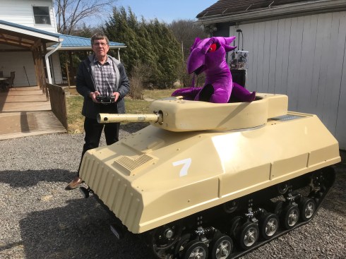
Thirty years ago, I attended a wedding in California where I rode in a tank that fired tennis balls. Ever since, I have wanted a tank. Today, I’m a retired accountant and I’ve finally purchased a Scorpion Mini Tank and this is my blog about purchasing and modifying it.
Clicking on a picture will usually enlarge it. Escape to get back to text.
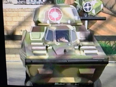
1990 tennisball tank 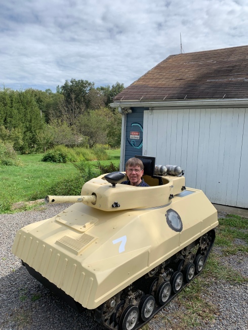
Scorpion MK3 at our farm
Research
When I set out to find a tank, the first thing I noticed was that lots of people were building there own tracked vehicles. As this was beyond my expertise, I searched the internet for off the shelf tanks. A used military surplus tank runs about $250,000. A Mud Trax starts at $40,000. The Rampage is really cool but only made for the military. The Chinese Fighter Tracks was priced under $10,000 but hard to import.
Research Notes 8/2019:
Argo information: Frontier 600 6×6 $10,000
Skid plate $310; Tracks $1,870 Plastic to $4,368 Rubber; ROPS $1,869
Lite Trax MTX-R (Mud Trax)
Utah Manufacturer says they start at $36,000
Ken at 704-279-5736 in NC says $38,900 plus freight from Utah
Paintball Battle Tanks (British manufacturer of Scorpion MK3)
http://www.paintballbattletanks.com/ 0044 (0)208 4326423
The Combat Zone (Georgia park with Scorpion tanks)
108 Godley Rd Bloomingdale Ga 31302 912-675-9952
https://thecombat.zone/
OSG Paintball (NH paintball park with Scorpion tanks)
David Preston 1 800-707-7529 https://www.osgpaintball.com/
1053 N Barnstead Rd, Center Barnstead, NH 03225
Fighter Trax
The max speed is 7km per hour. We have no US distributor yet. hdtk-200 do not produced any more, you can see if you are interested with DXTK-180. The price of DXTK-180, the FOB China port price is USD5200, to door freight is about USD1200. You can find how is the tariff from local custom clearance agency after Trump increase the tariff of goods from China. Any further questions, let me know. Pearl Zhao
Fighters All-terrain Vehicle Technology Co., Ltd
Cell/We Chat/Whatsapp: +8615350592434
Web: www.fightertracks.com
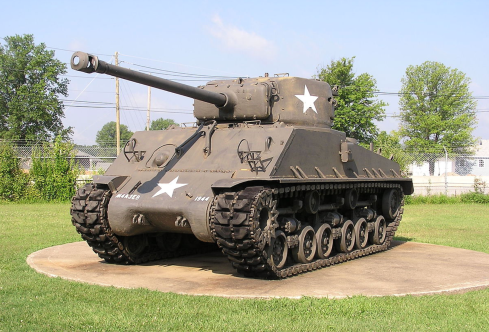
Sherman Tank $250,000
Too expensive, too heavy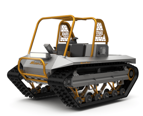
Mud Trax 
Polaris Rampage
only for the military
Scorpion MK3
I finally found a British tank manufactured by Paintball Battle Tanks. It’s a single person steel chassis tank with a fiberglass body and a very clever easy glide turret system. It opens like a clamshell and drives like a zero turn mower. It’s a true tracked vehicle with independent tank suspension with steel belt rubber coated tracks. It’s powered by a 500cc Briggs and Stratton engine. It has a max speed of 8mph and weighs about 1100 lbs. It’s 6.8’ long and 3.74’ wide. The US distributor is Armourtrax and it sells for about $13,000 plus shipping and tariffs.
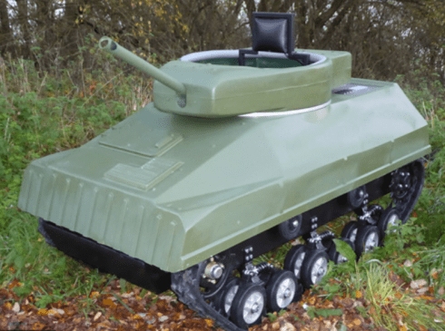
Scorpion Mk3 body 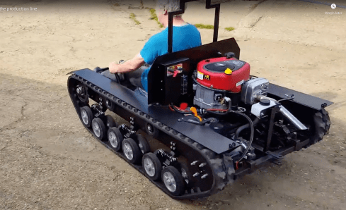
Scorpion MK3 engine 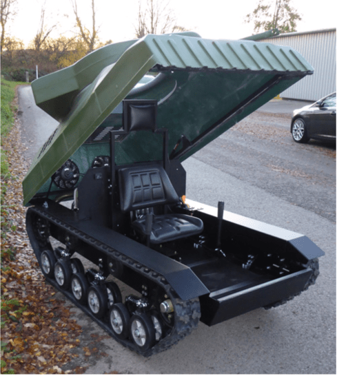
Scorpion MK3 clamshell
Scorpion Notes: 8/2019
I found Susan at Armour Trax through the Paintball Battle Tanks website which has a very responsive chat. Susan told me they expected their first shipment soon. She said there was a paintball park in Georgia and one in New Hampshire that had purchased tanks. Susan expects to take a tank to a trade show in Tennessee in February (2020). Susan said she would send me her standard letter.
Here is my standard letter:
My name is Susan, my husband Anthony and I just became the US distributor for Paintball Battletanks in December (2018). Our company is Armour Trax and we are based out of WI (south of Hudson). Our role for this company is to help facilitate sales and inquiries in the US. The tanks take approximately 3-4 months to build and ship to the US. Pricing is as follows: 1 – 2 tanks: $13,000 each; 3 – 9 tanks: $12,500 each; 10+: $12,000 each . The manufacturer requires a 70% deposit (to begin the order process) and then the remaining balance, prior to shipping. Shipping costs vary, depending on how many ship per container and then US shipment on top of that. I have a contact with a shipping company, who can give ball park estimates ahead of time and precise costs 2 weeks prior to shipment. We estimate shipping for 10 units to cost somewhere around $3,000 – $4,000 total.
http://www.mini-tanks.us/scorpion-mini-tank-specification.html
https://armourtrax.com/#about-1
Please let me know if you have more questions.
Thank you so much for your interest!
Susan, Owner, Armour Trax http://www.armourtrax.com/
**If you’d like me to price out the laser tag module, please advise and I’ll have David and Keith work something up for you.
OSG Paintball
Armour Trax, unfortunately had no stock so I contacted the paintball parks that Susan had said already had Scorpion tanks. OSG paintball is the largest paintball field in New England with 11 venues on 43 acres. David was very helpful and offered to sell me a used Scorpion Mk3 with only 8 hours on it. Nancy and I hitched up the trailer to the farm truck and headed to NH taking the 12 hour northern route through the Green Mountain National forest. It was beautiful but we decided to take the southern route home with the tank. David put us up in his massive 10 bedroom farmhouse and we discovered that he has a theater company (Hampstead Stage Company) as well as the paintball business. David toured us around his facility and we demoed the tanks and I purchased tank #7 and we headed home.

OSG Paintball 
Loading the tank in NH
OSG Notes 9/2019:
The Hampstead Stage company is a non profit celebrating 32 years. (2019) 1-800-619-5302. David hires professional actors and sends them out in pairs in Priuses to libraries and schools all over the country. His massive barn is full of sets and costumes and was a wonder to behold.
They are used and hours range from 7 to 14. Very lightly used. They were imported last year (2018) and stored. They each have a custom electric sensor so you know when the tank has been hit. Fully set up with dual air tanks and lines. Optional netting. We identified a couple weak points on the design and remanufactured parts and installed them. These tanks are an amazing marketing tool and a showstopper .
David included a dual tank Ninja 4500 Nlite 90 paintball system with an Eclipse Emek PAL marker, paintballs and the tank netting.
Here is a list of the OSG modifications:
Added larger gas tank, battery blocks, remote kill switch
Rewelded the control mounts and added steel pins to control sticks
Added two side hit sensors and a sensor computer and hit indicator
Replaced the battery, starter button and added a battery cut off switch
Replaced the wiring with heat resistant wiring
Loctighted lower wheels (Upper wheels need some play)
Removed decorative exhaust to improve engine performance
Refinished the back panels
Suggested modifications:
Battery terminal boots
Better fan cooling system
Stronger gas struts
OSG Tank Video: https://youtu.be/i2F1KOcOTXk
Trip Home
OSG quoted us $900 to deliver the tank and we did a lot of research to determine the best way to transport it. We wanted to go and see the tank in New Hampshire so we were going to make the trip either way.
The tank is 6.8 feet long and 3.74’ wide and 4.49’ high. It weighs approximately 1,102 pounds. The tank would have fit in the trucks 8’ bed but the truck couldn’t handle the weight. We looked at Uhall prices and finally took our old trailer which had a ramp. The trailer is 5’x10′ with a GVWR of 2,990 pounds. We had to get the lights fixed on the trailer so it was street legal.
It is 616 miles from Emlenton, where we live, to OSG in New Hampshire. We took two days to make the trip home from New Hampshire to Western Pennsylvania. We discovered that the blue straps (used in shipping the tanks) were not strong enough for the twelve hour trailer ride so we used chain through the front sprockets tensioned with the blue straps. We spent the night at the “Newbury Inn” in Brookfield Connecticut.
The next day, just after entering Eastern Pennsylvania, we stopped at the Pennsylvania visitors center to recheck the tank. When we looked under the truck we noticed the gas tank was on the ground. A helpful trucker suggested we use a ratchet strap to hoist the tank off the road and we then drove to a nearby garage to get a new retainer for the truck gas tank. What a blessing that the gas tank didn’t rupture.
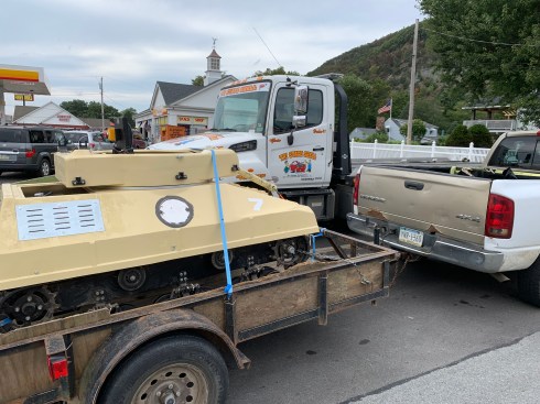
Note PS91 on the tow truck 
Truck gas tank with new retainer
As Purchased
When we arrived home, late Friday night, I noticed it had no lights as I maneuvered it off the trailer and parked it in our garage. That weekend I had a bunch of stuff going on at church so I read the manual. Monday, 9/9/19, I put the tank back together. I mounted the two air tanks, the screening, the paintball marker, the hit computer and light. Here is the tank as purchased. (Click on picture for full view.)
Marker 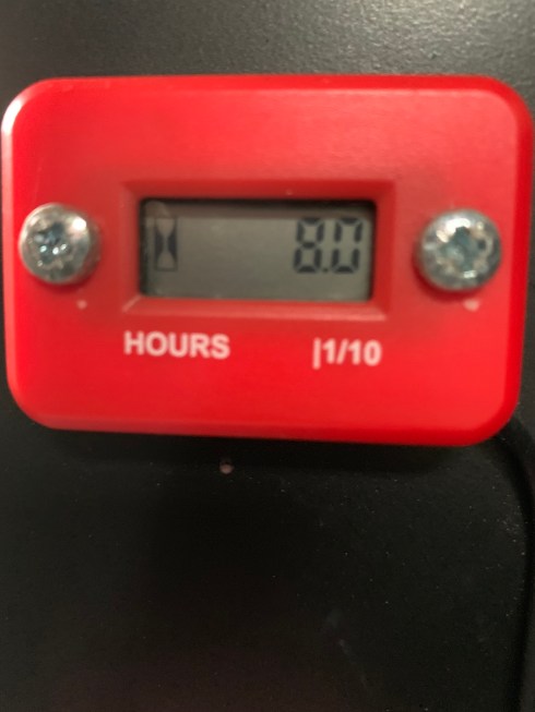
Hour meter 9/9/19 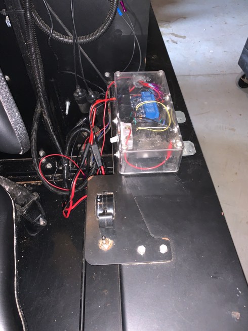
Brain (Hit computer) 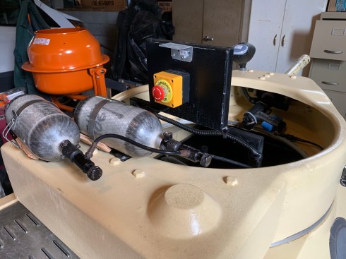
Dual air tanks 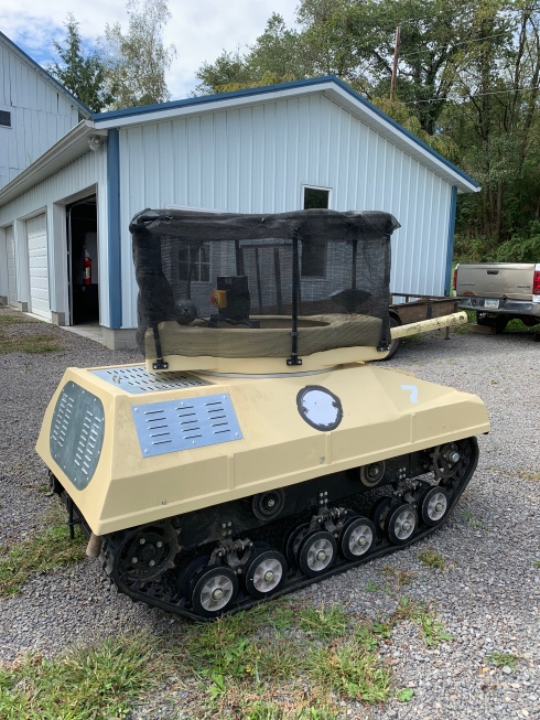
MK3 as purchased
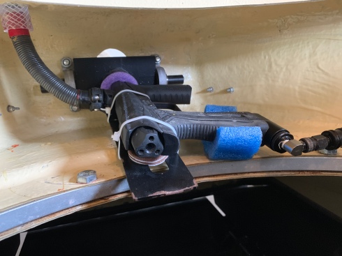
Turret Modifications
The first thing I did was remove the netting and the brackets that held the netting frame to the turret. (I wasn’t planning on being a target so I didn’t need the netting) Next, I removed the dual tank system and mounted a single tank inside the turret. I also removed the brain and the hit light, after testing them to make sure I understood how they worked. My first addition was a targeting camera on the canon which required mounting a battery in the back of the turret and a TFT screen in the front of the turret next to the marker. This was followed by a lot of research and documentation.
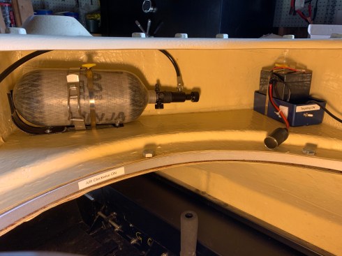
Single air tank and battery 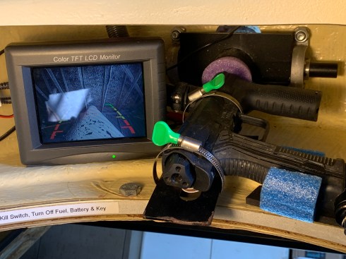
TFT targeting display
For the targeting display I used a EXP1250 12v 5ah battery. Amazon cost $17.49. I charge it with a Stanley BC209 tricked charger. Amazon $16.82
For the camera I used a RAAYOO LOO2 backup camera. Amazon cost $16.99. I used this one because it can be configured not to reverse the image. It puts out Yellow RCA video and runs on 12 volts DC.
For the display I used an old TFT display I had in stock. It measures 6.5” wide by 5” high and had a tripod mount which made it easy to mount to the turret. I used a foam pad. Amazon has one for $29.99 Padarsy 7” 800×480 TFT Display. B Qtec has a monitor and camera set for $27.99.
For the clamps I used Dreamtop 10 pack hose clamps 4.3” for the air tank and battery and 2.5” for the marker. You can get a 10 pack of 5 each for $11.89 from Amazon. They have thumb screws which will break but are nice if you are gentle with them. I used a standard hose clamp for the camera.
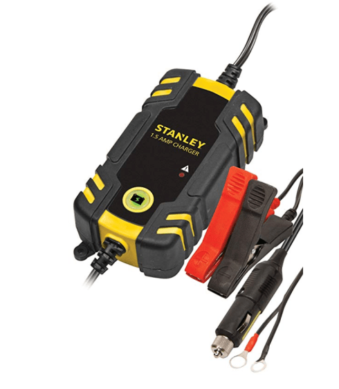
Trickel charger 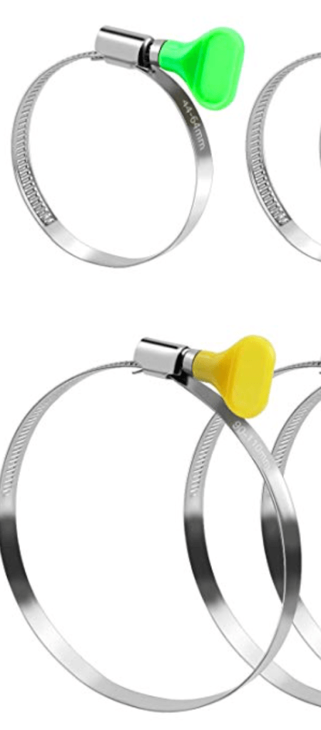
Clamps 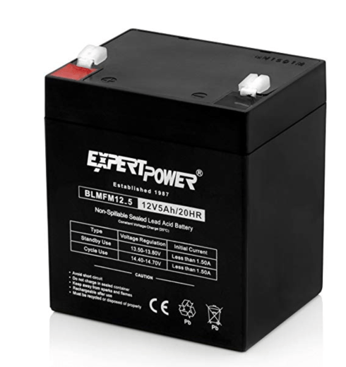
Turret battery 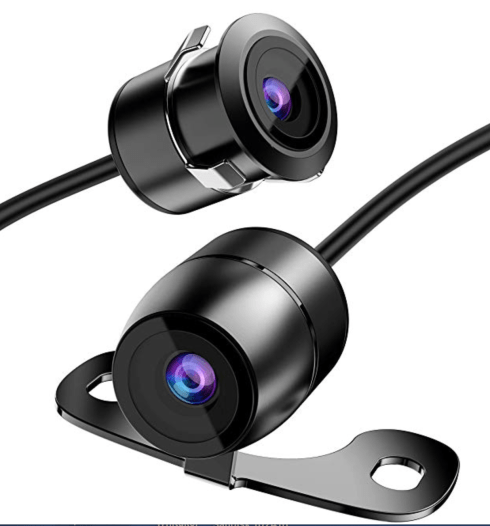
Targeting camera 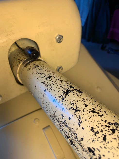
Camera mounted
Research notes 9/2019
Track adjustment:
Manual suggests 0.4” from mud guard (pressing up)
I measured the Left track at 1” no pressure and the Right at 5/8”
Fuel:
Use 87 unleaded with Stabil which counteracts the ethanol.
Turret battery:
12.85 initial battery voltage
The camera and monitor draw approximately 0.6 amps
Main battery:
12.6 volts initial voltage
Marker:
The marker is an Etha Eclipse Emek Pal version SN 63002.
They run on approximately 450-550 psi. Use only lithium grease.
Air System:
I purchased some pressure meters and the tank runs 3k psi regulated to approximately 500 psi. The marker seems to leak air but the air line looks good and it has a slide valve which will hold pressure. The tanks need to be retested every 5 years. I’m using an Killhouse Weapons straight remote line with slide check. Amazon $29.99.
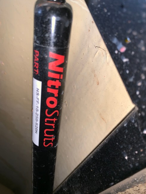
Struts:
I did a lot of searching online for a US version of the struts. They are made by Nitro Struts in Britain NS-FF-10-250-920. (Steel, 9.84 stroke, 21.85 overall, 920 Newtons force (206 lbs). They are expensive ($35ea) as is the shipping ($70). I will check with a local auto parts store.
Paintballs:
I tested the marker and it worked well with the targeting camera. I am using .68 caliber winter load. GI Sportz Cryofill Frostbite .68 Caliber approximately $0.025ea
Top Removal
We had to make some special tools to remove the top of the tank. First we made a strut prop (note it rests on the metal frame). Then we removed the struts. Next we removed the prop and lowered the clamshell and then removed the back pins. We designed a hoist bracket and used an electric hoist to remove the top. Again we were careful to only load the steel frame not the fiberglass.
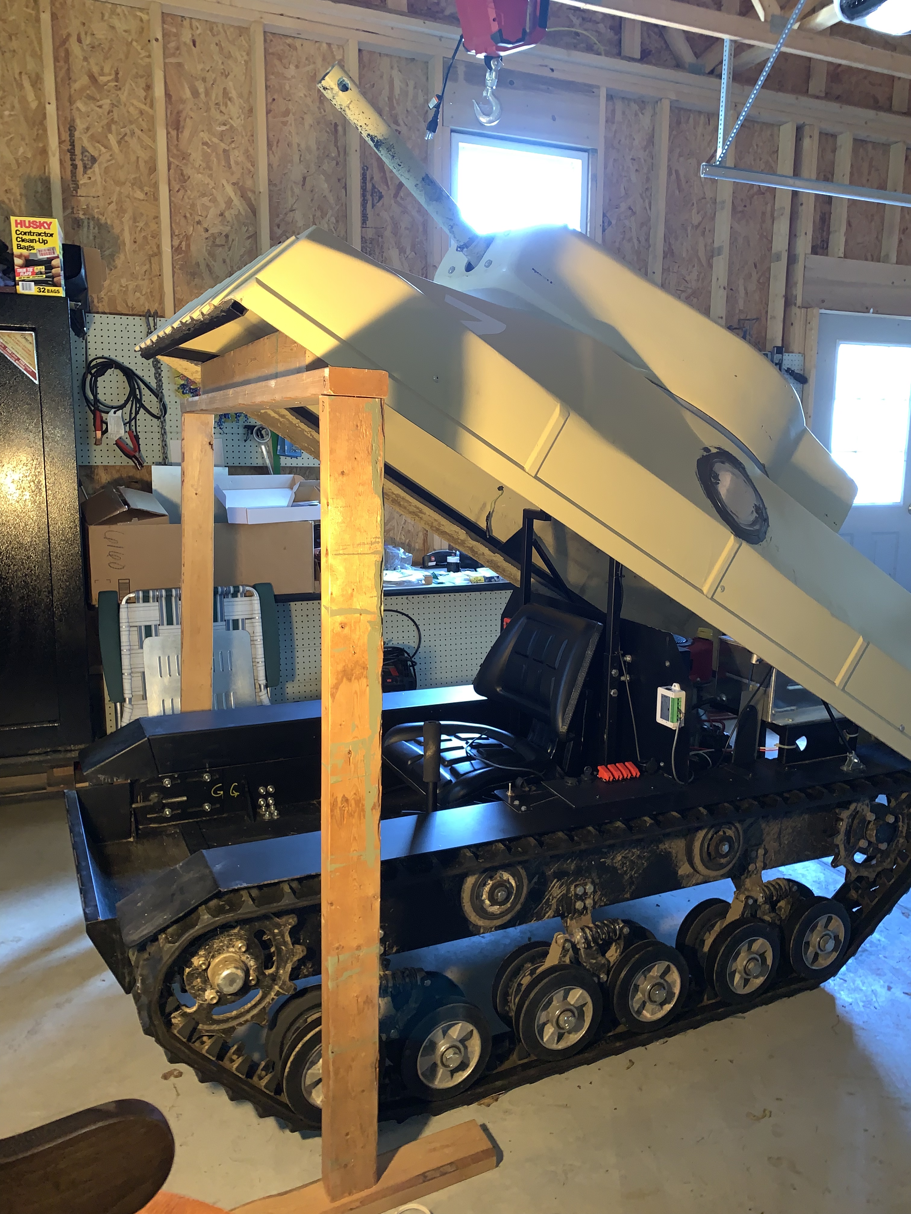
Strut prop 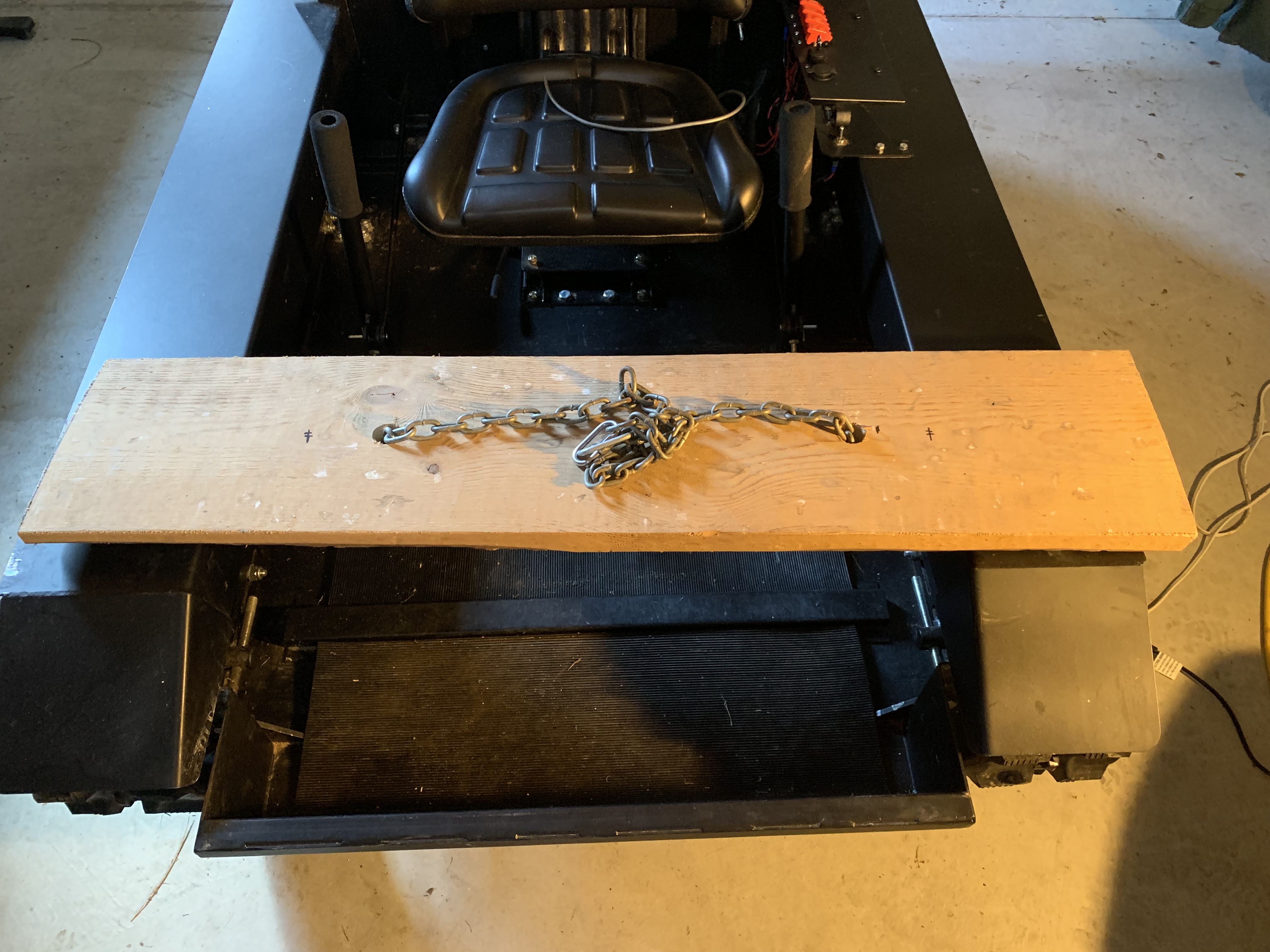
Top hoist bracket 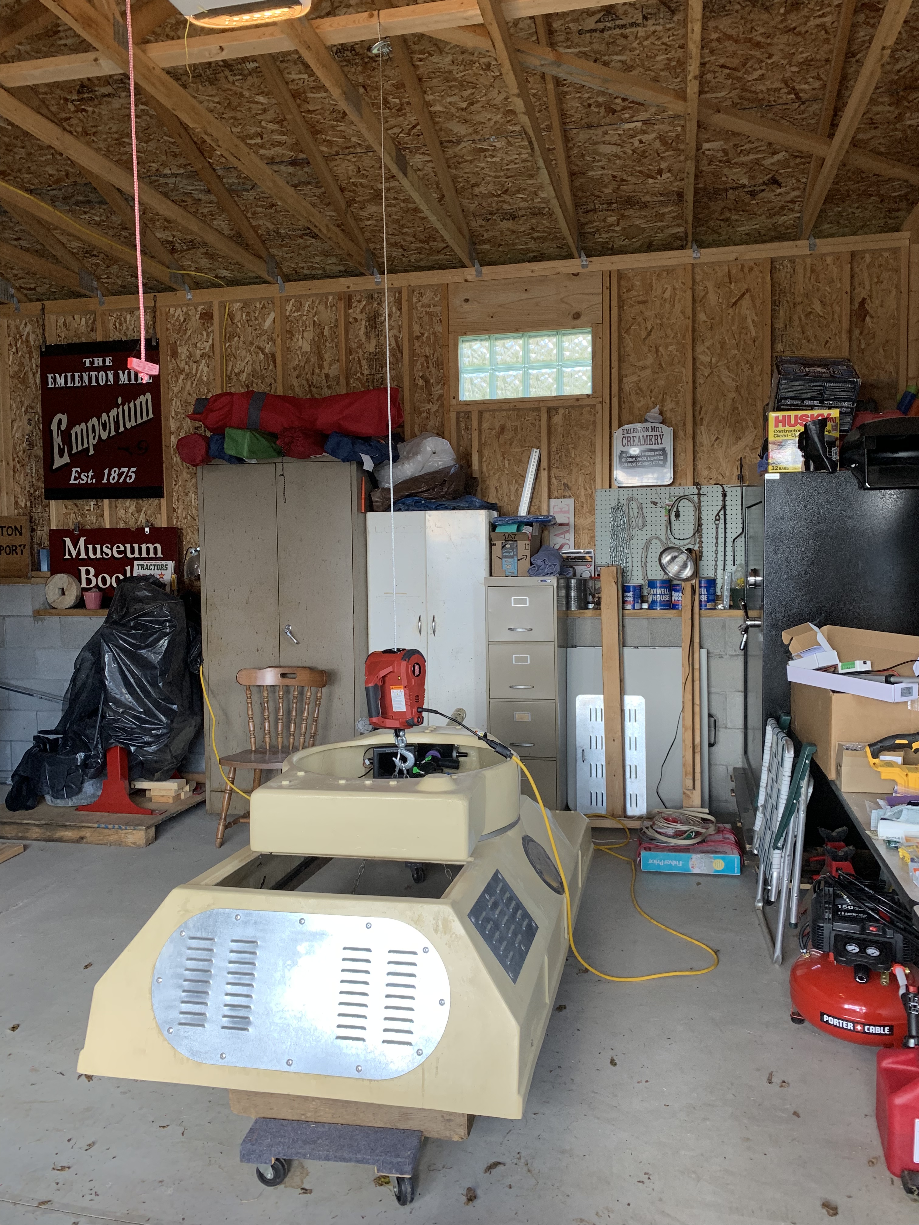
Top hoist 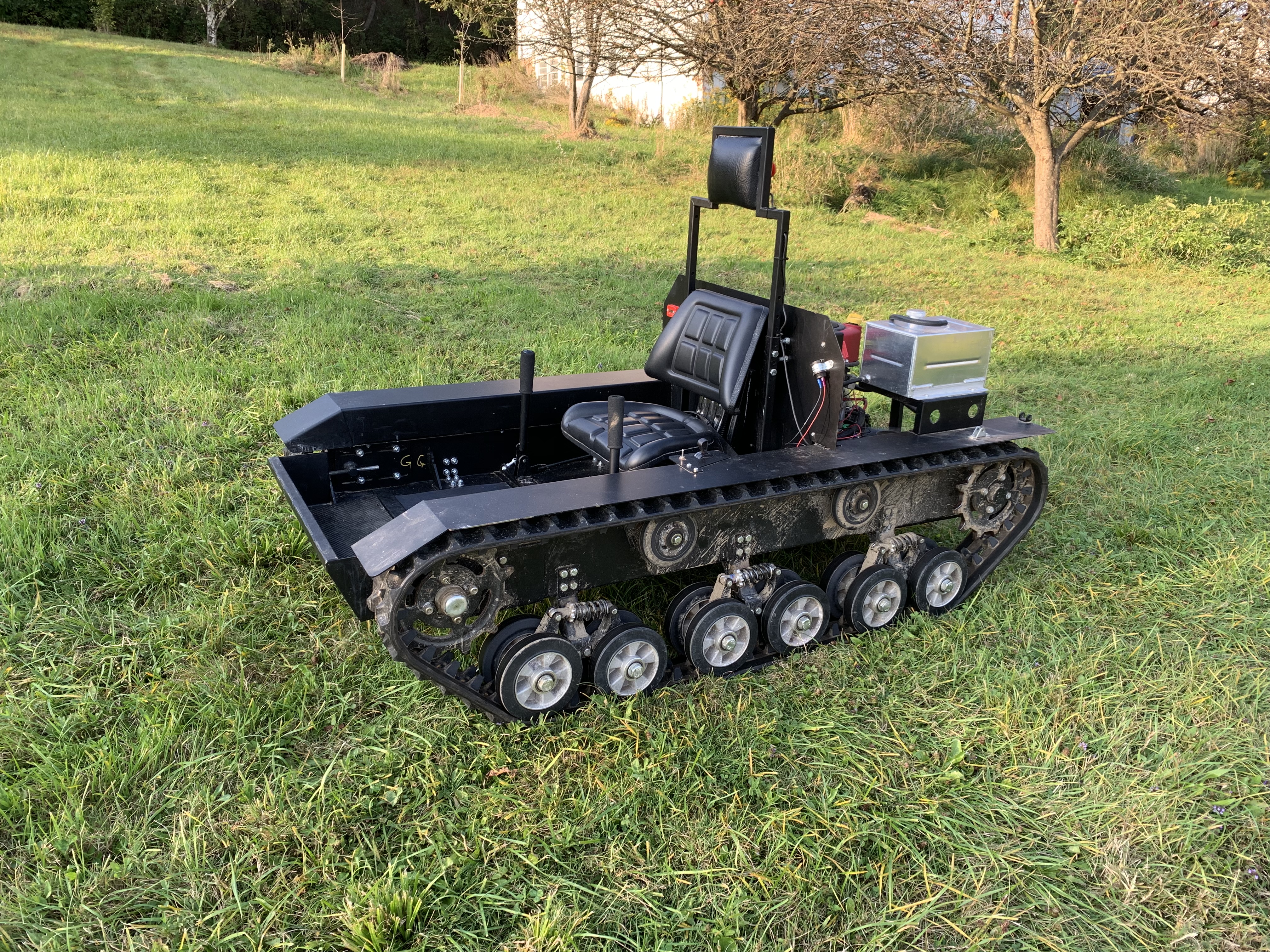
Top off
Strut Notes: 9/2019
Rear body pins: I replaced the bolts and nuts in the two back clamshell hinges with clevis pins and cotter pins.
Nitro Struts: I removed the lower screw pin and then unscrewed the strut from the upper bracket.
It is also necessary to disconnect the fans and the side sensors to remove the top of the tank. I rerouted the fan wires around the gas tank so they didn’t hang over the hydro units.
Strut 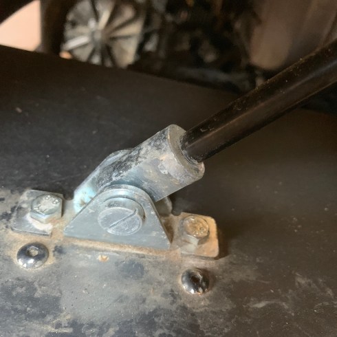
Lower strut bracket 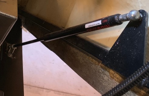
Upper strut bracket
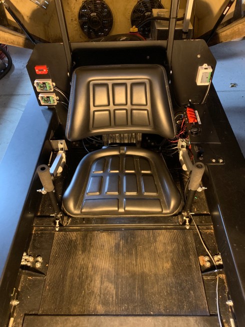
Electrical Mods
I have made a number of electrical mods to the tank based on my usage of it. I’ve moved control of the tank from the engine compartment to the cockpit. (I understand that in a rental market this may not be wise) I have reconfigured the main power wiring so that battery positive only goes to the main red key switch and it only feeds the starter solenoid and the fuse block. Everything else is after the fuse block. I removed the OSG remote starter module and switched the OSG remote kill switch at the rear panel.
The cockpit control panel has a key switch to energize and start the engine. Four toggle switches control the fans, lights, strut lift and the brain. Two twelve volt outlets are provided. One switched by the red main key switch and one switched by the accessory position of the starter switch. LEDs indicate energized circuits.
I added a large red rubber boot to the positive battery terminal.
The white box on the left is the lift controller. Switch on top.
The controls on the right are the original engine throttle and kill switch.
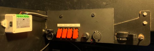
Cockpit controls
Straight Terminal protector boot 4-6 ga $6.99 Amazon.
Switches: Nilight 90014E 12v20a SPST rocker switch with hood. They looked military. Amazon $9.63 for pack of 5.
LEDs- FICBOX 6mm 12v LEDS. Amazon $9.99 for pack of 5.
Starter Switch Sierra MP41040 15amp 12v. Amazon $16.82
It controls both the engine power (grey) and the start solenoid.
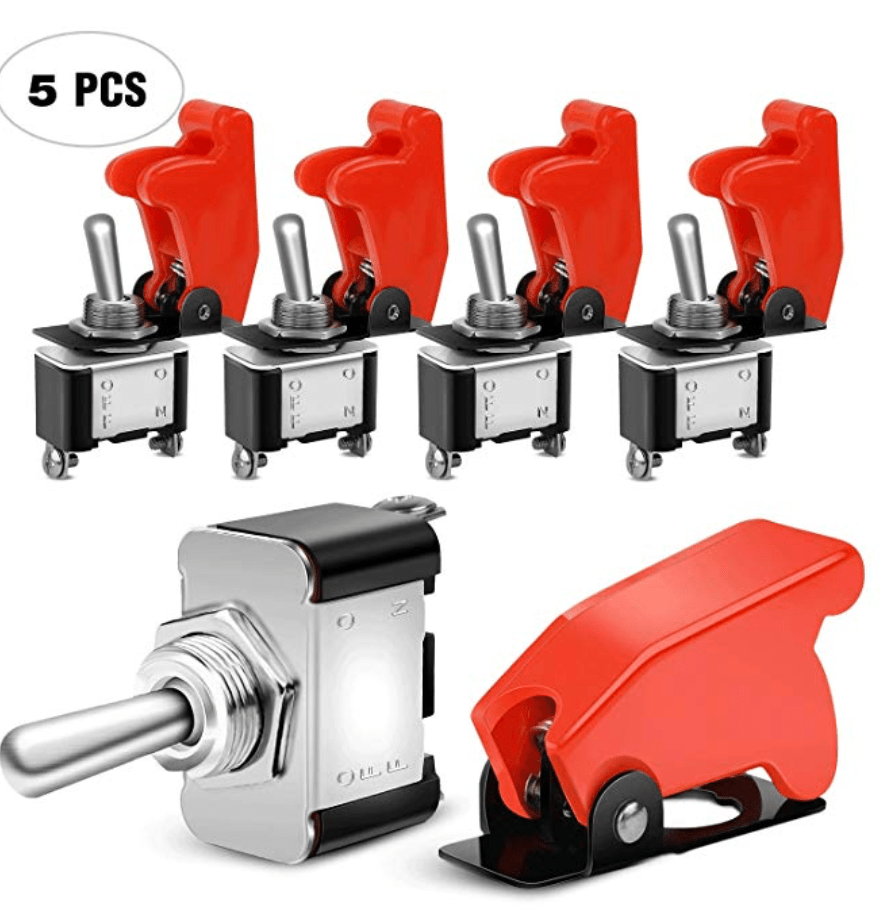
Switches 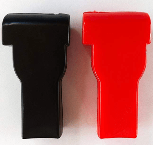
Battery Boot 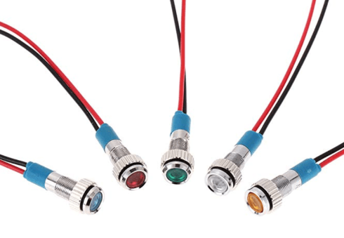
LEDs 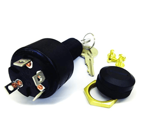
Starter switch
Lights: Yitamotor LED light bar 18w 6” flood Amazon $15.99 for a set of two. I mounted these on the front of the tank body.
Kill switch: I believe that the Kill switches are (closed to stop engine) and therefore in parallel- not in series as shown in the Mk3 manual. OSG added a remote kill switch module to the power panel and I repurposed the fan switch to control the Kill module.
Power panel: note the red boot on the battery and the repurposed remote kill switch power.
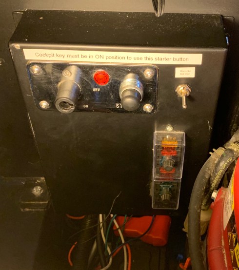
Power panel 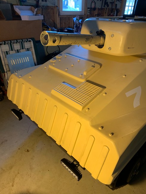
Lights mounted 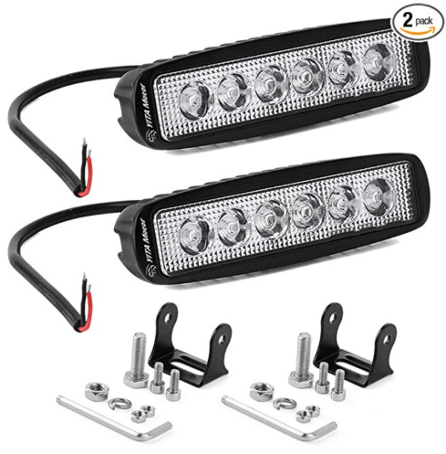
Front flood lights
I repurposed the fuse box to include the modifications to the tank. Starter (red) and Fuel (gray) are now handled by one fuse because of the combination starter switch I am using. This fuse also handles the switched accessory 12 v outlet which I use to meter the battery.
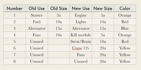
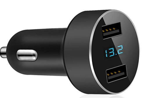
Meter: Lihan Dual USB charger and meter 4.8a. Amazon $10.99
I find this very handy for monitoring main battery voltage.
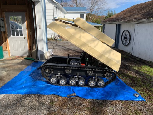
Lift Mod
The modification that has been the hardest so far has been the addition of a linear actuator to lift the clamshell. While I was researching the struts, I started thinking about ways to lift the clamshell. I researched hydraulics and pneumatics and settled on a linear actuator (motorized screw). I am using one that costs $38 and lifts 900 newtons (225 lbs). To complicate things, I wanted to be able to manually lift the clamshell as well as have the actuator lift it. This meant that only the top of the actuator would be connected to the clamshell. The bottom had to dock into a receptacle. This presents a very interesting problem in three dimensions. It took me four tries before I settled on a bungie cord to help guide the bottom of the actuator into the receptacle.
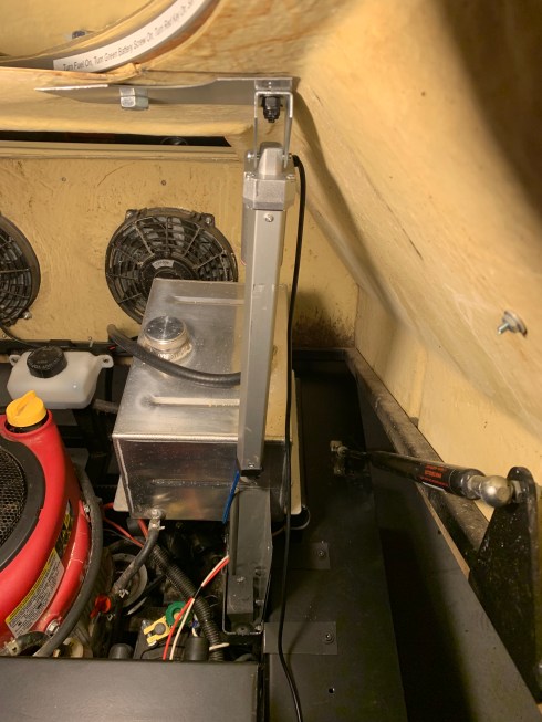
Lift mod lower dock 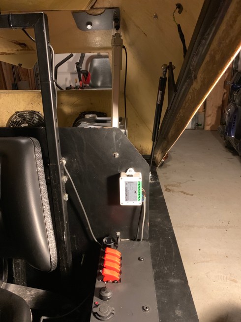
Lift mod upper bracket
The linear actuator is made by Homend GR 9863 12v DC, 225 lbs, 10” stroke, 25 sec full length, retracted length 14.8’, extended length 24.8”, 3 amps. Cost $37.95 Amazon. I picked this one because it closely matched the struts in size and capacity.
The controller is Eco-Worthy wireless motor controller. (this could also be done with a simple DPDT switch. It comes with a remote control and there is also a manual control on the top of the box. Cost $20.99 Amazon.
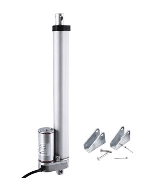
Linear actuator 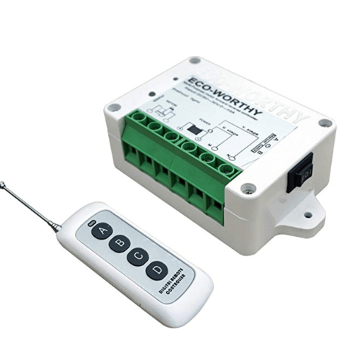
Controller 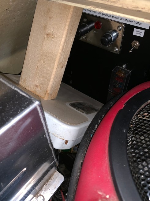
Measured force 200 lbs
Operation
Preflight checklist:
Obviously you should read the manual before use. Ear protection.
Check engine and transaxle oil level (1/2 full – don’t overfill)
Walk around checking tracks and suspension.
Verify that the lift strut is in the retracted (DN) position
Operation- Starting:
Check that the fuel is on.
Check that the red power key is on.
Switch on the remote kill if you are using it.
Set the throttle to idle or choke if engine does not start in cold.
Turn the cockpit key switch to on (red light comes on).
Turn the cockpit key switch to start. Engine should start.
Use the fan if it is a hot day (only run when engine is on).
Use strut lift and lights only when engine is running.
Throttle up to fast. (Throttle does not effect ground speed).
Avoid zero speed turns. (control sticks pointed opposite)
Operation – Stopping
Throttle down to idle and run at idle for a few seconds.
Shut down fans and other accessories.
Run the engine at slow speed for several seconds.
Toggle the kill switch until engine stops.
Turn cockpit key to off
Turn red power key to off.
Turn off fuel if not using the tank for a while.
End of day checklist:
Clean mud off wheel bogies and debris from inside tank.
Check grease nipple cap on front hubs is in place.
Check the drive belt for damage. (once the engine is cool)
Check front and rear sprocket bolts are tight.
Check bogie wheels are tight and not damaged.
Leave the clamshell open for storage with the lift strut DN
The Brain
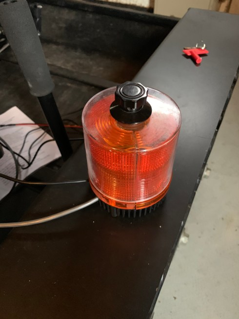
OSG noticed that it was hard to tell when the tank had been hit by a paintball so they designed a hit computer called the Brain. It uses an Arduino type computer and relay board to sense the change in voltage across a pressure sensor mounted on the sides of the tank. When the tank is hit the orange strobe light is latched on by the computer. OSG noted that it is complex and sometimes flaky. It does lend itself to future upgrades like hit counts.
Tank with Brain and light 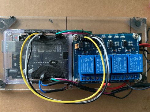
Brain Computer
The Arduino board is an Elegoo Uno R3 ($11.96 Amazon) with a 4 realy module ($7.99 Amazon). The orange strobe light is also available from Amazon for approximately $25.00. The system requires a separate 9v battery pack in the Brain case to power the Arduino. Each of the two side sensors is handled independently.
Arduino
Let me say up front that I’m an Arduino novice and I don’t have access to the actual programming of the Brain but here is what I can see from the setup. (the Brain is actually an Elegoo Uno R3 – a Chinese Arduino)
Power is supplied to the logic board from a 9vdc battery box which has a small switch on the battery box and a large white switch on the side of the brain case. (The strobe is reset by cycling power (turning the white switch off) to the Brain.)
The two side sensor black leads are wired to the A0 and A1 analog inputs both of which are individually tied to ground through 270 ohm resistor. This is presumably to keep the analog input from floating high.
The two side sensor red leads are wired to the D2 and D3 digital inputs which seem to be at +5vdc. (They may just be providing a 5vdc source.)
Therefore, I would assume that the analog inputs are measuring the voltage change across the pressure sensor.
The relay board gets it GND (Black) from the logic board and its Vcc (White) from pin D8 (digital) of the logic board. This is presumably so the brain can conserve power by turning the relay board off when not in use.
Relay one of the relay board receives its trigger (Yellow) from D9 (digital) of the logic board. When the SPDT relay is energized it closes the 12vdc path between the tank battery (12vdc) and the strobe light.
Based on the above, I assume that the Brain looks for a drop in the voltage across pressure sensor (a hit) and then latches the relay on. The Brain may also be doing some debouncing of the signal to assure a clean hit. (note: OSG rewired the 12v accessory outlet to be switched by the Brain)
Pressure Sensor
The hit sensor on the tank is made with a Force Sensing Resistor which has IEFSR written on it (Interlink Electronics). They seem to be available on the internet from companies like Digikey for about $12.00. The sensor is 1.5” square and comes with a connector. It is sandwiched between two 7.5” diameter plates of aluminum with a 1/16” thick rubber ring between the two plates. It is held to the tank with two screws and then the joint is waterproofed with a rubber type compound. The rubber compound can be removed with mineral spirits and elbow grease. When measured installed it varied between 270 ohms and about 1000 ohms. When measured without the cover plate it measures around 50 ohms to about 100,000 ohms. (A much wider range.) My research shows they are only accurate to about 10% and they seem to give inconsistent results.
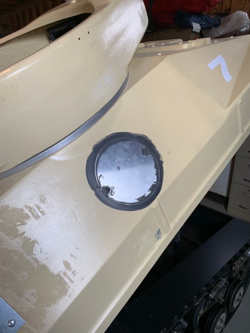
Hit plate on the tank 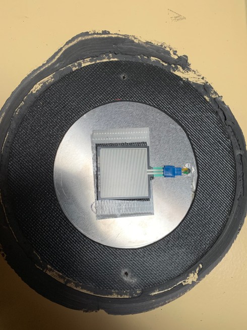
Hit sensor with top plate removed
Brain Revisited
As an exercise, I decided to see if I could fit the Brain into the orange strobe light. I also wanted to add an adjustment to address the differences in the hit sensors. The sensors tend to trigger on around 270 ohms and off around 1000 ohms but it varies. I chose a Youngneer 12v relay board ($1.50 Amazon) which would fit inside the strobe light and mounted a 1K potentiometer on the top of the light to adjust the sensor trigger point. It doesn’t have the flexibility of the Arduino and you would probably need a relay board and potentiometer for each sensor but it could still all fit in the strobe light.
The knob on the top adjusts the sensor trigger point
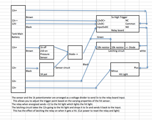
Schematic of revised brain (Click to enlarge)
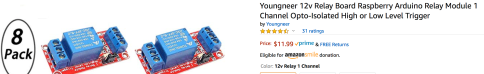
Younger relay board
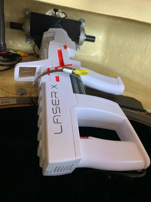
Laser Conversion
Laser X makes a long range blaster that can easily replace the paintball marker is the tank canon. It’s available from Amazon for about $30.00 and is compatible with other Laser X products. I tested it in daylight at 100 feet and it works great. It comes with an attached target sensor which could be mounted on the tank turret. Unlike some of the smaller Laser X guns its reload function is activated by pulling back the forward stock which works with the mounting shown below. It claims 300’ range which is further than I can see the target.
Remote Control
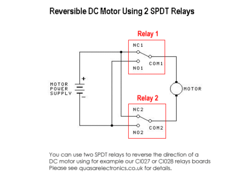
The tank provides an excellent platform for robotics. My first experiment was to control the two control sticks using the same linear actuator I used in the strut lift system. To accomplish this I needed a remote control that could reverse the actuator. Solidremote makes a nice remote control box for under $20.00.
This is how to wire the Solidremote 202U wireless controller to control a linear actuator to control the tank. Amazon Kit-1 $18.99
- Wire the linear actuator to the two relay commons
- Wire +12 to the 2 relay NCs and to one relay board power
- Wire -12 to the 2 relay NOs and to the other board power
If the actuators works backwards just reverse the actuator connections to the 2 relay commons. I wired the actuator Blue to relay one.
In this setup the actuator stays on approximately 1/2 second after you release the Button. Using the Homend 12v 6” stoke actuator Amazon $35.95 you get approximately 1/4” per 1/2 second pulse.
This is how to program the Solidremote 202U wireless controller to control the right linear actuator. Amazon Kit-1 $18.99
- Set the dip switches to 1-off, 2-off, 3-off (pulse mode)
- Hold P1 switch and press Button B (Forward) until sig flashes
- Hold P2 switch and press Button D (Back) until sig flashes
- Test the relays (LEDs in receiver) and the transmitter Buttons
You program the left actuator in the same way.
You can not use two key fobs simultaneously (eg: pressing a button on each of two key fobs does nothing. (the signals cancel out)
But you can program a button on a key fob to activate both the left and right relay units. Thus pressing A will cause both actuators to move forward and pressing C will cause them both to reverse.
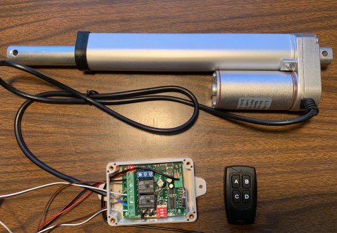
Actuator, controller and key fob
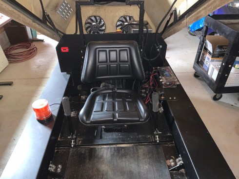
The actuators are mounted on either side of the seat and connect to the control stick with a 6mm x 65mm (2.5″) bolt and 2 each 6mm hex nuts. They can be easily removed for manual control. I would suggest using the remote kill system when remotely controlling the tank in case it gets out of control. I used 16g steel from Tractor Supply for the brackets and mounted them so the back clevis pin of the actuator was 10″ from the firewall and the front pin was 11″ above the floor on the control stick. This allows for maximum forward speed and actuator cutoff at both extremes within the arc of the control sticks. It takes some practice to control the tank using the key fob but it works well.
Actuators and controllers mounted in the tank
Maintenance
Maintenance should be performed on the vehicle every 50 hours.
OSG suggested every 15 hours.
There is a time counter attached to the firewall to the right of driver.
Maintenance includes the following:
Replace the oil in the engine every 50 hours.
Replace the oil and filter in the trans-axles every 75-100 hours,
then every 400 hours.
Replace drive belt if it shows any signs of wear.
Check the suspension rockers are greased.
Check the front wheel hub bearings are greased.
Check the health of the bogie springs,
Ensure they expand when the weight is released.
A full service should include checking all bolts to ensure they are tight.
Replacement Oils & Other Consumables
Hydro-Gear Transaxles – 20W – 50 MINERAL OIL
Briggs and Stratton Engine – 5W – 30 FULLY SYNTHETIC OIL
Drive Belt – Timing Belt 1440-8M-20 (6257)
See the manual for details on servicing.
Armourtrax did a comprehensive maintenance workup on four tanks it purchased from OSG. (These tanks had from 6 to 16 hours of use)
Not everything listed was required for each tank. Here is a list of what they did:
Standard Maintenance:
- Changed the oil (full synthetic 5w30)
- Changed the filter
- Cleaned the air filter
- Cleaned spark plug
- Lubed track idler bearing
- Checked and added Hydro oil
- Tightened battery terminals
- Tightened bolts
Special and one time maintenance:
- Inspect and reroute fuel tank vent with cable ties
- Adjust idle mixture
- Inspect exhaust and replace screws with rivets
- Tension tracks
- Replaced fuel shutoff valve (it was leaking on some tanks)
- Welded engine mounts (they found some bolts were loose)
- Installed dedicated choke cable (choke was not engaging)
- Replace fuel line (it was rubbing against the access panel)
- Lined access hatch with foam to protect fuel line
- Replaced rivet on hydrostatic arm
- Replaced 4 sprocket hub and lug nuts
Parts
Air Tank- Ninja 4500 Nlite 9090cu in 4,500 psi Amazon $184
Battery – Exide SX151R 340a, $135.00 aaautostores.com
Battery (turret)- EXP1250 12v 5ah battery. Amazon $17.49
Belt 1440-8m-20 (6257) $20 Amazon
Belt Spring- garage door spring (perhaps trampoline spring)
Bogie springs- HAO TAI Suspension 1200LB/IN
Bogie wheels (lower)- ELASTIC 200/50/140 (bolt TY8.8)
Bogie wheels (upper)-TENTE 160/40/80 (Bolt TY8.8)
Brain- Elegoo Uno R3 (arduino) and Elegoo r4 relay board
Camera (backup)- RAAYOO LOO2. Amazon cost $16.99.
Engine Briggs and Stratton Intek 4-175 500cc 17.5hp $585
Engine Oil -5w30 synthetic
Fans- 12v 80w each 6.6a (drain battery fast)
Fuel- 87 octane with Stabile (1/2oz/gal) to counteract ethanol
Hydraulic hose-1620psi EN854 071017
Hydraulic oil- 20w50 mineral oil
Hydrogear- ZT3400- see Amazon $500-800 each
Lights: Yitamotor LED light bar 18w 6” flood Amazon $15.99
Paintball marker- Etha. Eclipse Emek Pal version $400
Paintball lubrication- lithium grease only
Paintballs- .68 caliber (app $0.025 each) GI Sportz Frostbite Starter Switch Sierra MP41040 15amp 12v. Amazon $16.82
Struts- Nitro NS-FF-10-250-920N (10-250 is the strut Ref) $32
Strut lift- Homend GR 9863 12v DC, 225 lbs, $37.95 Amazon
Strut Control- Eco-Worthy wireless motor controller $20.99
Track- steel belted rubber (approx $1000/each)
Turret lubrication- WD40
Upper guide wheels- heavy duty dolly wheel (blue roller)
Winterizing
Next week they are calling for snow, so I took advantage of the warm weather to wash off the underside of the tank. The tarp is because Nancy has been washing her black walnuts and the driveway is a bit messy. This actually worked nicely. I could clean the treads and then move the tank forward a bit and clean them again. By the time I got into the garage the treads were all clean. I then washed down the tarp and backed the tank back out to dry.
Briggs and Stratton suggests the following for its engines:
1. Add fuel stabilizer (Stabile) to reduce the risk of buildup.
2. Change the oil and the filter (if equipped).
3. Remove battery, store the battery in a cool, dry place.
4. Clean the undercarriage.
5. Store your lawn mower in a cool, dry place.
Autonomous Tank Project-
GPS and Rangefinder controlled
Now that the tank can be remote controlled using linear actuators the question became: Can we make it autonomous? This actually has two levels. The first is computer controlled using a GPS to navigate between waypoints. The second level adds a rangefinder to avoid obstacles.
To this end I was referred to a website called ardupilot.org which has all sorts of interesting articles and software for making things autonomous. A great deal of this is devoted to drones and airplanes but there is a section on autonomous rovers. Utube has also been a good source of information although both are somewhat daunting in the amount of information available.
The first hurdle has been to understand the lingo. What is an ESC? What is FPV?
The second hurdle is understanding the technology. Is my linear actuator brushless or brushed? Should I be using a linear actuator that has feedback and/or limit switches or a linear servo?
The third hurdle is software. Which groundstation software should I use based on what kind of computer hardware I am using.
The fourth hurdle is hardware. Which flight controller? Which transmitter and receiver?, which GPS?, which motor control board?, which camera system?, which telemetry system? which sensors?
And this is just the start…
Needless to say there is a steep learning curve here for someone who has never been part of this scene. I’ll try to take you through some of my education as I pursue the goal of the autonomous tank.
LINGO
UGV- Unmanned Ground Vehicles are also called rovers. They are a subset of Drones. The brain of a drone is called an autopilot. It consists of a flight stack (firmware) running on vehicle controller hardware.
PX4 is an open source flight stack (firmware). It grew out of the Pixhawk project at ETH Zurich. PX4 is part of Dronecode, a non profit organization administered by the Linux foundation. Dronecode includes Qgroundcontrol and Dronecode Camera Manager and the Mavlink messaging protocol.
Qgroundcontrol is the Dronecode ground station. It can be used to flash (load) PX4 onto vehicle control hardware (Pixhawk), setup a vehicle, get real time information from a vehicle and execute autonomous missions. It runs on Windows, MacOS, Linux and IOS (over WIFI). MissionPlanner is another very robust Ground Control software that runs on Windows.
Chibios Ardurover v4 is another flight stack that is widely used. It’s compatible with Qgroundcontrol or MissionPlanner which runs on Windows.
Pixhawk is an open autopilot hardware. It can be flashed (firmware loaded) with Ardurover or PX4 from Qgroundcontrol or MissionPlanner.
Sensors: PX4 and Ardurover use sensors to determine vehicle state and minimally require a gyroscope, accelerometer, magnetometer (compass) and barometer. A GPS is needed to enable automatic modes.
Data Telemetry radios can provide a wireless MAVlink connection between ground stations and a vehicle running PX4 or Ardurover. FPV (first person view) cameras can also use the Mavlink protocol and Dronecode Camera Manager to provide video streaming to the ground control station.
PWM- Pulse Width Modulation is the common form of control between a RC radio and its control servos.
RC: Radio Control systems manually control a vehicle. They consist of a transmitter and a receiver. PX4 and Ardurover do not require RC for autonomous missions but it seems like everyone uses one.
ESC: An Electronic Speed Controller converts a signal from a flight controller (like Pixhawk) to an appropriate level of power delivered to a motor. PX4 and Ardurover support ESCs that take a PWM (pulse width modulation) input.
BEC: Battery Elimination Circuit- a switching voltage regulator. It is typically used to reduce the main battery supply to the 5v needed for logic circuits.
Drivers: Software that run on ground station computers that facilitate serial port connections to the Mavlink telemetry radios, etc.
OpenTX: Firmware that runs on RC radios. One thing that they can do is run scripts that alow the Pixhawk to send and display telemetry data on the RC radio.
Yaapu: Yaapu provides a script that runs between the FrSky RC radio and the Pixhawk. This requires a special cable.
Arduino: We have discussed arduino microcomputers before but I am using one to control the motor controller that controls the linear actuators that control the tank skid steering.
Technology- Actuators
The first piece of technology I needed to understand was Actuators because that is how I control the movement of the tank. I currently use simple, cheap $38 linear actuators but to use them with Pixhawk I will need to have them controlled by a PWM signal not relays.
Actuators have either Brushed or Brushless motors. Brushed motors (like the linear actuators I currently use in the tank) have two wires. Brushless motors use three phase and have at least 3 wires. (More wires if they have a feedback potentiometer).
The tank currently uses brushed motors in its actuators with limit switches. 150mm 6” stroke, 900N 225lbs $38 Homend GR 9863
The actuators can be driven with with a brushed motor controller.
(Servocity Actobotoics 605045 $100 (Dual)) In RC mode the controller requires a PWM signal varying from 1000-2000 microseconds. (1000us 100% one direction, 1500us no movement, 2000us 100% in the other direction). This controller has three other input modes: voltage, servo and split. It runs on a single voltage 12v.
Pololu makes a VHN5019 Dual brushed motor controller for $50 that is also Arduino compatible. They have a great manual for the board on their site which included arduino test software. My first tests were using the $38 actuator and an arduino to translate the PWM signal from the Pixhawk to the linear actuator but this doesn’t center the thrust.
Later I decided on a Linear Servo Brushed replacement for an RC servo
Servo City L16R140-150-6 140mm (5.5”) stroke (200N) 44lbs
12v input with 5v BEC and internal controller $90.00
It’s more expensive but doesn’t require the Arduino and there is no problem centering the actuator because it is a servo.
Technology- FPV
FPV is First Person View and it requires a number of components.
Camera: HS1177 indicates a 28MM square camera. They go down in size from there: Mini, Micro, Nano. AIO cameras (All in one) vary in shape and size (typically 12mm square) and typically include the VTx (transmit system). Pick your aspect ratio based on the goggles you may purchase. Latency is the biggest enemy in FTP. CCD cameras typically have the lowest latency (app 20ms) FOV (Field of view) is typically 2.8 but Go Pro offers a wider 2.5 lense. OSD (on screen display) lets you add text to the picture like battery level. (Getfpv.com Runcam Eagle 2 $53)
Video Transmitters (VTx): A VTx takes a camera signal and transmits it to a receiver (RTx) on the ground. They are rated for power. Typical power is 25mw to 800mw. When flying in groups they recommend 200-250mw. 5.8ghz is the typical frequency but lower frequencies 2.4 & 1.2ghz go further. Standard resolution is 600TVL (TV Lines) 768×494 pixels. HD Video is 1080p or 720p. Higher resolution is more data and can cause more latency. Always have the antenna attached before powering. Getfpv.com Lumenier TX5G6R 600mw 5.8ghz FPV $30)
Radio Control (RC) Transmitters: Hall effect gimbals are more precise and last longer than potentiometer gimbals. Mode 2 is the most popular mode. Pitch and Roll on the right. 433, 900 & 1.3ghz are typical long range frequencies. 2.4ghz is the most popular. Lower frequencies need larger antennas. Open TX and telemetry are good options to have.
Video receivers VRx: There are single antenna and dual antenna (Diversity) systems. Getfpv.com ImmersionRC Diversity $150.00 Single $60.00
To get analog video from the VRx to USB for the the ground control station you need a Easycap board Amazon $15.
Technology- Arduino
Arduino is a small single board open source electronics platform. Amazon $17, the power supply is $7. Arduino.cc has a web based software editor that is easy to learn and use. You will need to set up a free account and then you can program the board by connecting it to your computer via a USB cable.
Void setup:
Void Setup is technically a function that you create at the top of each program. Inside the curly brackets is the code that you want to run one time as soon as the program starts running. You set things like pinMode in this section.
Void Loop:
After creating a setup() function, which initializes and sets the initial values, the loop() function does precisely what its name suggests, and loops consecutively, allowing your program to change and respond. Use it to actively control the Arduino board.
// means ignore this line (for documentation)
#include is used to call an outside library
I++ is short for i=i plus 1
Delay(2) means delay 2 milliseconds (1000ms=1 second)
Technology- Pololu
Pololu Dual VNH5019 Motor Driver Shield for Arduino $53.00
This is a dual motor driver board that works with an Arduino. It can handle loads of 6 amps at 24 volts. It comes without the headers soldered in so some soldering is required. (Try not to make the mistake I did and solder the headers on the wrong side of the board.) If you wish to power the Arduino from the Pololu board you cannot exceed 12 volts (the Arduino Max voltage). There are a bunch of other potential problems with powering the Arduino from the Pololu board (which requires a jumper) so I suggest not doing it. (see the pololu PDF on working with an Arduino) dual_vnh5019_motor_driver_shield.pdf pg 14
The motor controller can also be used without the Arduino. In this case logic power 2.5-5v is applied to VDD. A PWM signal controls the speed and the direction is determined by INA (clockwise) and IN B (counterclockwise) The EN/Diag pin is used to enable (Logic high) the motors.
Here is some simple arduino code to run the linear actuator backward:
#include “DualVNH5019MotorShield.h”
DualVNH5019MotorShield md;
void setup()
{md.init();
}
void loop()
{
md.setM1Speed(-400);
// where +400 is forward, -400 is backward and 0 is stop
}
Technology- Pixhawk
I purchased the Pixhawk drone controller from Amazon from Sologood as a kit for $129.00 It included the GPS, safety button, buzzer, PPM (translates PWM to PPM signals), Power module, Telemetry radios, OSD module (displays flight telemetry), I2C splitter, RGB/USB Extender module. Sologood customer service seems very responsive but the kit comes with no documentation. I ended up sending it back and getting another to solve a problem.
I am using QGround control on a Mac running El Capitan. I spent a day trying to get the Pixhawk to be recognized by the MAC USB only to find out that the Micro B USB cable I was using (I tried 3) was only for charging. After I found a good (data) cable the Pixhawk connected fine. In the process I replaced the FTDI driver 2012 with 2017 and installed the Silicon Labs CP210X telemetry driver. They are found either in Libray/Extensions or System/Library/extensions.
I connected up the button, switch, gps and telemetry radio and plugged the Pixhawk into the USB port of my Mac. It asked to update the firmware which you do by unplugging from the USB and then plugging in again. I chose PX4 and the rover airframe.
To calibrate the sensors they suggest placing the GPS and the Pixhawk on a piece of cardboard so as you rotate them they will stay aligned. Note the arrows on each unit should face the same direction.
I have changed to the Ardupilot Chibos rover in an attempt to get the telemetry radios working but ended up replacing them to fix the problem.
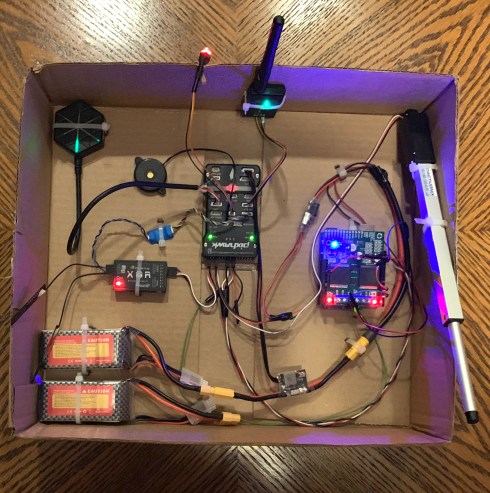
GPS upper left, Telemetry radio upper center, test servo on right side
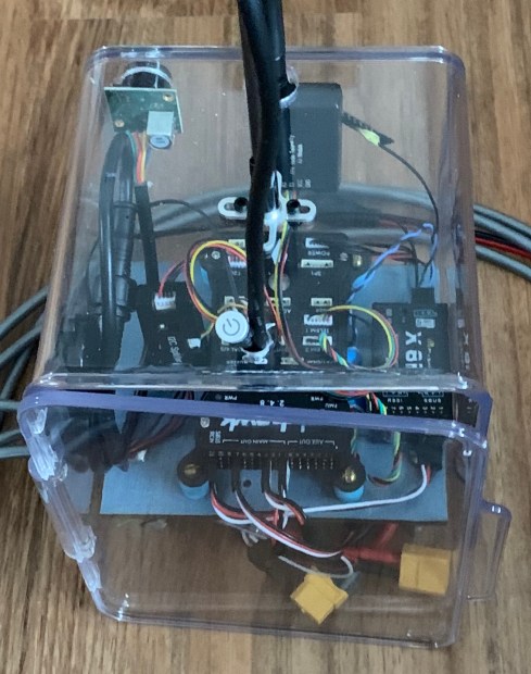
Red hardware arming switch upper center, buzzer is the round item
Frsky XR8 receiver and Yaapo telemetry cable to Telemetry port 2
Two 1.5ah 12v batteries bottom left (I only use one at a time).
Batteries connected to a BEC which is connected to Pixhawk. 5v
Battery also connected to a 2nd BEC that powers the Pixhawk rail 5v.
Battery also connected to the motor control board 12v. (right side)
The Arduino is below the motor controller and is powered from rail.
(The Pixhawk servo rail +5v is not connected to the Pixhawk logic.)
The whole system is tied down to the box for easy rotation calibration.
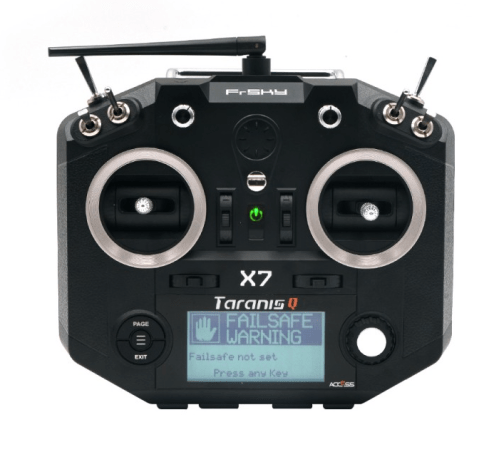
Technology- RC Radio
I’m using the Frsky QX7 transmitter ($138 Amazon) & the X8R ($37 Amazon) receiver. There is a three pin Sbus cable that plugs between the Receiver and the Pixhawk. On the Pixhawk side it goes into the RC connector on the servo rail (not SB but RC) with the black GND wire toward the top of the pixhawk. On the X8R the cable goes into the Sbus connector located as a fourth row under the servo rail with GND toward the outside.
Turn on the transmitter, skip past any errors, hit the center left button to get to models, rotate the right button to get to a new model, hit page to create a new model. Name the model.
Scroll down to RXNUM and select (right button) Bnd (bind). Select Ch1-8 telem and it will start beeping. Hold down the FS switch on the receiver and apply power to the Pixhawk. The receiver will start flashing. Let up on the FS switch. Disconnect power and then reapply power. The led will glow red. Exit out of bind on the transmitter. Turn off power on Pixhawk. Now when you power up the Pixhawk with the transmitter on you will get a green light on the receiver.
The servo rail on the X8R has signal at the top which goes to the orange wire on the servo.
To get to general setup press and hold the left button. If you want it to talk you need to purchase a micro SD card and download the sounds from Frsky. https://youtu.be/YD3ojhwVmrI has a good video about setup and changing the gimbal springs and battery. Blue Falcon also has a great series on the QX7 on YouTube.
Technology- Servos
The standard servo voltage is 4.8 V DC, however 6 V and 12 V is also used on a few servos. The control signal is a digital PWM signal with a 50 Hz frame rate. Within each 20 ms timeframe, an active-high digital pulse controls the position.
The pixhawk does not provide power to the servo rail from the power connector that powers the sensors. You can apply voltage from another source by using an unused position on the servo rail. There is mention of using a zener for protection so that the rail does not exceed 5 volts because the rail also provides backup power through a diode to the Pixhawk.
It seems to be ok to power the rail with 5v and also connect the usb to the computer for the ground control program.
In the radio setup you can see which radio transmitter control effects which ground control Name (eg: throttle). You can then go to the parameters list in ground control setup and find servos and assign a servo on the main output section of the rail to that Name (eg: throttle)
The pixhawk must be “armed” for the transmitter to run the servos connected to the Pixhawk. (you can, by the way, connect small servos to the receiver. (not sure about its current capacity) The pixhawk main led is blue when armed by ground control, additionally the arm button must be solid red for the servos to work.
To arm without ground control running you press the arm button until its solid red and then hold the right stick up. To disarm hold right sick down.
I set the radio to use Mode 2 and AETR. Then I set the RC Map to:
Pitch (Elevator)=4, Roll (Aileron)=3, Throttle=2, Yaw(Rudder)=1
This makes it so Left Stick FB is Roll Ch3 & Right stick FB is throttle CH2
This makes the Pixhawk servo outputs RC CH3= Right and RC CH1=Left
This sounds a bit weird but I will explain more later in calibration.
Groundstation- Computer control
I have tried 3 ground station software packages. They are all free.
QGroundcontrol 3.5.6 runs on Windows and Mac and it runs fine on my late 2015 iMac running El Capitan 10.11.6.
I had to add two drivers to Library/ Extensions:
FTDIUSBSerialDriver.kext 5/9/2017
SiLabsUSBDriver.kext 11/3/2016
It also runs on a MacBook Air Mid 2011 running Sierra 10.12.4
Library Extensions:
FTDI VCP Driver 2.4.2 5/9/1
Si labs legacy driver 2/28/19
I’m connecting in General/Autoconnect/ticked mode
APM Planner 2.0 also runs on both my macs.
uses cu.usbmodem1421 at 57000baud for directy USB connect
uses cu.slab-usbtouard for telemetry connect
Mission Planner runs on Windows and is supposed to run on a Mac using something called MONO but I couldn’t get it to work. My son has a windows machine and I really like Mission Planner on Windows. It downloaded the drivers automatically and seems to have a lot more diagnostic features then the other two.
C:\program files (x86) mission planner
Com3 57000 baud
Pixhawk Wiring
I’m using a Pixhawk 2.4.8 from Sologood (China) $128 Amazon
Unpack and check that the SD card is seated properly
Plug in hardware arming button (red left)
Plug in buzzer to buzzer port (I used the 1” round one)
Plugged M8N GPS to GPS Port (red left) and 12C port (orange left)
I later swapped this out for a Radiolink M8N SE100 $29 Amazon
They both seemed to work about the same.
Connected Pixhawk to USB on Mac (cord must be data not charging)
Launched QGroundstation 3.5.6
Settings/firmware update using Chibios Ardurover 4.0.0.0 standard
Shut down and unplugged the Pixhawk from the Mac USB
Installed the Telemetry radio on the Pixhawk Telem1 (red left)
The yellow wire goes to the RX on the airside radio
Plugged the other telemetry radio into the Mac USB port
Connected the Sologood BEC to the Pixhawk power and the battery
Launched QGroundcontrol (QGC) on Mac
Powered up Pixhawk (telemetry radios solid green when connected)
Ran a manditory calibration on the sensors using QGC
Moved the system outside to get a good GPS lock (GPS Flashing)
Shut down system and installed X8R Receiver (see Radio section)
Connect X8R to Pixhawk RCin with black wire towards the top of
Pixhawk
Calibrated the radio and radio switches with QGC
You can temporarily turn off the safety system in QGC to quiet things
Shut down the system and installed the test servo and the second BEC
The second BEC powers the Pixhawk servo rail 5V
You may need to set your Servo CH8 function to RCin in parameters
You may need to tell the radio what switch or rotary controls the
Channel
Power up the system and test the servo (Hardware arm the Pixhawk)
Shut down and installed the Yapoo telemetry cable (see radio section)
I used Telem 2 but I think you can use Serial 4/5
(set serial protocol to 10)
Rangefinder and MODES
The difference between Manual, Auto (GPS mode) and Autonomous depends on the rangefinder. In manual mode the RC radio controls the tank using the radio control sticks to control the tank control sticks. In Auto mode you set waypoints in the ground control software and the tank follows the waypoints using the GPS. In Autonomous mode you need the rangefinder to keep the tank from running into obstacles.
I am using a Maxbotix MB1242 I2CXL sensor $35 which is designed to work with the Pixhawk. I also needed to use the I2C splitter that came with the Pixhawk.
The ardurover software handles two rangefinder modes: Dodge (slide) where the tank tries to avoid an obstacle in Auto Mode. Simple (Stop) in Arco, Steering and Guided modes where the tank stops when it sees and obstacle. The range is displayed in the ground control software.
Here are the parameters:
RNGFND Trigger CM specifies how far away
RNGFND Turn ANGL -450 to 450 (large values are aggressive)
RNGFND turn time how long to keep turning after loosing object
RNGFND Debounce higher number reduces false positives but takes longer
Set:
Rng fnd Max 700cm (23 feet)
Rngfnd Min 20cm (7 inches)
RNGFND Type =2 (maxbotix I2C)
Avoid enable use prox sensor (2)
Avoid behave= 1=stop, 0=slide
Avoid Dist max= 1-30 meters set at 5 meters
Avoid dist margin- 1-10 meters (in GPS stay away distance) set at 2m RNGFND1_ORIENT=25 (Down- needed for Yaapu- only down works)
Yaapu only looks for and displays the down oriented rangefinder
Calibration
Mandatory Calibration:
- Calibrate the accelerometer
- Calibrate the Compass (best outside away from metal)
- Calibrate the radio and switches
- Safetys
- Flight Modes (I use Manual, Hold (center sticks) and Auto)
- Power Monitor= Analog V and C; Set your battery capacity
GPS works best outside or near a window
It not only needs a 3D lock but ALRS needs to be good also
If you can’t get into auto mode it’s probably ALRS GPS not stable
Failsafe trigger0x1 means RC radio not connected.
Software:
I’m using a pixhawk 2.4.8
I’m using Misssionplanner 1.3.7 on a windows PC
I’m using a Taranis QX7 Inputs= AETR Mixer= AETR to a X8R receiver
I’m using Ardurover Chibios Ardurover v4.0.0.0 standard Rover
Radio:
Model Name: Pix
mode 2: AETR
Roll (aileron) Ch 1
Pitch (elevator/ pitch) Ch 2
Throttle (speed/ Throttle) Ch 3
Yaw (rudder/Yaw) Ch 4
Switches:
A (small left) forward is Manual, center is hold, back is Auto) CH5
D (small right) run programs (not implemented yet) CH6
F ( Front Left) Arm (up is arm) CH7
Right Rotary Ch 8 runs the test servo actuator
Left Rotary controls sound volume
PARAMETERS
Parameters: (You set these in the ground station software)
To use skid steer you must set the following servo functions:
Servo1_function = Throttle Left 73
Servo3_function = Throttle Right 74
PILOT_STEER_TYPE = 1 (two paddles) (I have also tried =0)
Cruise_throttle = 50% Cruise_speed 2.0 m/s
Mot_thr_max = 100% Mot_Thr-Min =0%
Frame_class= Rover
Mot_PWM_Type = normal (0)
Radio Calibration: Left stick FB is Roll Ch3,
Right stick FB is Throttle Ch 2
Pixhawk servo outputs: RC Ch 3= right and RC ch 1= left
RC Map: Pitch=4, Roll=3, Throttle=2, Yaw=1
Servos set to Min=1100, Trim=1500, Max=1900
I only arrived at these parameters after much trial and error.
You set the radio for AETR but then need to use the RC Map
to get the two sticks to control the linear servos properly
Safetys all off (safetys are mostly for flying machines not rovers)
Power Capacity 1500 mah (this was for the test setup)
Flight Modes 1&2 Manual, 3&4 Hold, 5&6 Auto
Serial ports:
Serial 0 = mavlink 115200 baud
Serial 1 = mavlink 57600 baud
Serial 2= FRSky Sport pass through 57600 baud (set protocol to 10)
Serial 3= GPS 38400 baud
Serial 4&5 none
RC7 option 41 arming (this allows arming from the radio switch)
Final Assembly
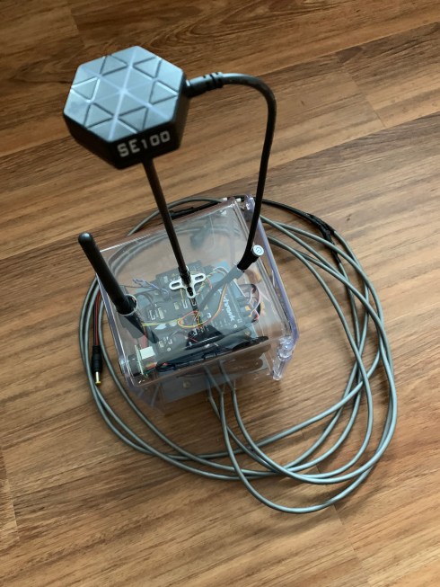
After having calibrated and tested the system in the cardboard box, I installed it in a plexiglas housing. The GPS is mounted above the box for best reception. The second antenae sticking up is telemetry. There is a rangefinder mounted on the front of the box. The Pixhawk and the receiver are mounted in the middle with the BECS at the bottom. I am using two BECS. One for the Pixhawk and one for the servos (directly connected to the servos not the servo rail. The buzzer and the arming switch are also used. The three cables that come out of the box are for the two servos and power. 3/9/2020
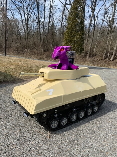
Testing
The video below is from my second test set of the tank in Auto mode. The first test set was a one waypoint test where the tank traveled the length of my driveway from “Home” to “Waypoint One” in a straight line. It went fine. The second test set (see video) is a two waypoint test with a 90 degree turn at waypoint one. I have cut off the video before the tank overcorrects and fails the test. The next section will be on “tuning” the tank. This is where your modify the parameters in the ground control program. In my case to make the pivot turns less aggressive.

